
Modern composite materials, like carbon fiber reinforced polymers (CFRP), are extensively used in automotive, wind energy, and aerospace applications due to their light weight and exceptional mechanical properties. However, their heterogeneity and anisotropy pose significant challenges for nondestructive testing (NDT), which is critical for ensuring structural integrity. Traditional ultrasonic inspection is slow and requires contact with the sample, often involving water. Infrared methods, such as pulsed thermography, offer a fast, large-area, non-contact alternative for detecting defects.
Thermal tomography represents a significant advancement in this field, utilizing a diffusive process where heat propagation through a solid is dampened as a function of location and shifted in time. This technique involves thermally exciting the specimen with absorbed radiation from sources such as Halogen lamps, leading to a time-dependent temperature change that is detected contactless with an infrared detector, such as a focal plane array IR camera. The process mirrors the physics of transient heat conduction or infrared waves, similar to classical active thermography, like pulsed thermography. However, standard IR methods are limited to surface-level or 2D results, making it impossible to determine defect depth. In contrast, thermal tomography allows for the analysis of the measured temperature field on the component surface, enabling the application of advanced numerical methods based on transient heat diffusion. This not only ensures reliable defect detection and identification but also provides 3D defect representation, facilitating the determination of absolute defect sizes and depths.
Photothermal Thomography
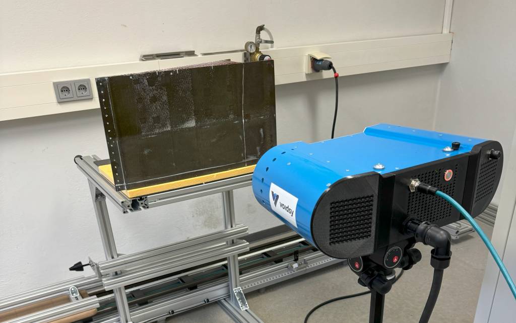
voidsy is an academic start-up of the University of Applied Sciences Upper Austria and initiated the product development of the photothermal tomography system 3D V-ROX. This system significantly improves NDT by offering accurate defect detection and quantification, in a contactless, fast and cost-efficient manner. The system consists of excitation units, a detector unit and an integrated computing unit. Due to its compact design and its low weight (<6kg), it is easily mounted on small robot arms or suitable for mobile, battery-operated applications. Even in manual inspection setups, its compact design facilitates quick setup without the need for alignment adjustments, thanks to its structurally fixed positions of the excitation and vision units.
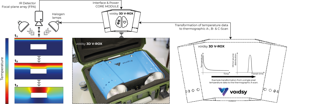
The inspection procedure using the 3D V-ROX system is schematically shown in Figure 1. The system employs two 2kW Halogen lamps for thermal stimulation of the inspected surface, while an IR camera captures the surface temperature simultaneously. The introduced heat propagates through the sample and if it interacts with a defect – such as a disbond or foreign object debris (FOD) in composites material – the propagation is disturbed and the surface temperature signal changes locally. These changes are often small and difficult to recognize; hence, the system transforms the measured signal into a corresponding mirror source distribution to enable photothermal thomography. The evaluation of a detector-pixel of the mirror source distribution provides an A-scan. For a defect-free sample and a measurement carried out in reflection mode, the A-scan shows a front wall and a back wall echo similar to ultrasonic testing. If defects are present, for example, the A-scan also shows intermediate echoes.
Use Case Aircraft Spoiler
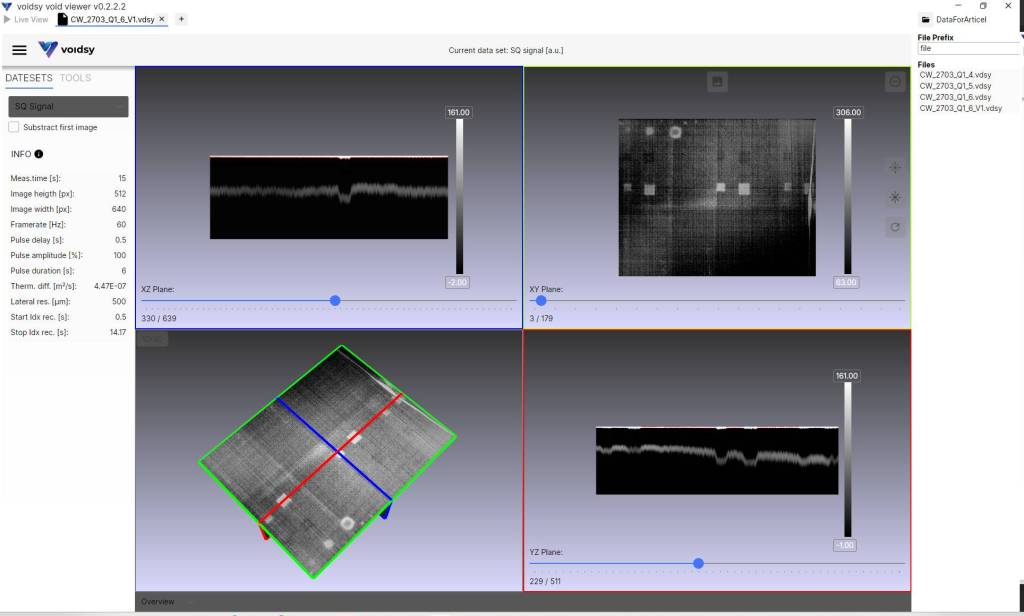
An exemplary practical use case is represented by the inspection of a CFRP aircraft spoiler (Fig. 2). The part, with a sandwich construction, consisting of CFRP skins bonded to a Nomex honeycomb core, was tested using the new system. The results, displayed in A-, B-, and C-scan formats, reveal foreign object debris (FOD) at various depths. These scans provide detailed insights into the integrity of the bond between the skin and core, and the thickness of the skin, identifying any material inhomogeneities.
Location: Wels (Austria)
Year founded: 2022
Founders: Dr. Holger Plasser, Dr. Günther Mayr, Dr. Gregor Thummerer, DI Gernot Mayr
No. of employees: 5
Commercial status: Revenue